Overview
After using a tiny LED screen as a digital clock that was too hard to read at a distance, I decided I wanted a bigger one and wanted to do it as a DIY project. This post details how I build my own powerful big RGB LED Matrix.
Required parts
Most parts were sourced from overseas where possible to reduce the total cost of the project.
| Part | Price ($AUD) | Link |
|---|---|---|
| Raspberry Pi 4 Model B 8GB | $123.00 | Core Electronic |
| Adafruit RGB Matrix Bonnet for Raspberry Pi | $29.65 | Core Electronic |
| P2.5 RGB LED Panel 320mm x 160mm | $58.00 | Ali Express |
| Ultra-thin switch power supply 5v40A200w | $13.87 | Ali Express |
| Australian Power Cord Cable AU (1.2M) | $4.24 | Ali Express |
| Heat-resistant silicone wire (14 AWG, 1 meter) | $2.80 | Ali Express |
| Heat-resistant silicone wire (20 AWG, 1 meter) | $1.08 | Ali Express |
| TYPE-C USB Plug Male connector | $2.65 | Ali Express |
| Male DC Female Connector | $3.03 | Ali Express |
| RICHMETERS RM113D NCV Digital Multimeter | $18.30 | Ali Express |
| Dual Wall Heat Shrink Tube (2 meters, 6.4mm) | $6.05 | Ali Express |
| Dual Wall Heat Shrink Tube (2 meters, 9.5mm) | $8.95 | Ali Express |
| Dual Wall Heat Shrink Tube (2 meters, 30mm) | $13.16 | Ali Express |
| Black Insulated Braid Sleeving (5 meter, 4mm) | $3.29 | Ali Express |
| Black Insulated Braid Sleeving (5 meter, 6mm) | $3.95 | Ali Express |
| Black Insulated Braid Sleeving (5 meter, 8mm) | $4.60 | Ali Express |
| Black Insulated Braid Sleeving (5 meter, 10mm) | $5.26 | Ali Express |
| Black Insulated Braid Sleeving (5 meter, 12mm) | $5.92 | Ali Express |
The total project cost ended up being: $307.80 AUD
However, it is important to note that the RPi being used for this project is overkill and was only used because I had one available already. Furthermore, the multi-meter, wiring and connectors can be reused for multiple projects and some purchases were completely unused. It is thus feasible to complete this project with a $150-$175 AUD budget with a more optimised parts list.
Circuit Diagram
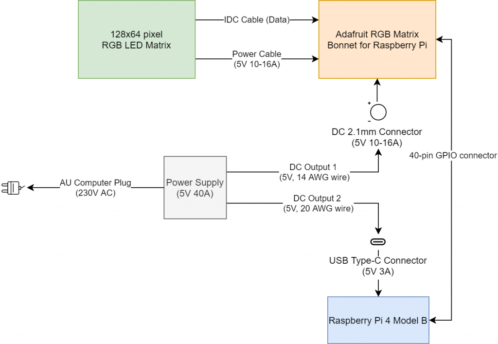
This is the final design used for the project. The idea is to have the LED matrix combine to become one component that is isolated from the power supply.
Process Breakdown
LED Matrix
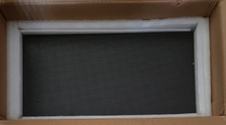
The RGB Led Matrix I used is a P2.5 matrix meaning each pixel is 2.5mm apart and the ideal viewing distance is roughly 2.5m away. The smaller the P number the higher resolution the LED matrix. The matrix has a resolution of 128 pixels * 64 pixels. Its physical screen size is 360mm x 160mm which is a larger size as far as single LED panels go.
The matrix has two cables which need to be connected. One for its data (via an IDC cable) and one for its power. As this is a larger sized panel, a significant amount of power will be required if you wish to avoid reduced brightness or flickering with all of the LEDs pixels on. The manufacture estimates the LED will draw between 10-16 A depending on the number of lit up pixels. Therefore, we need to provide it with at least 5V 16A of power to ensure it will work as intended in all use cases.
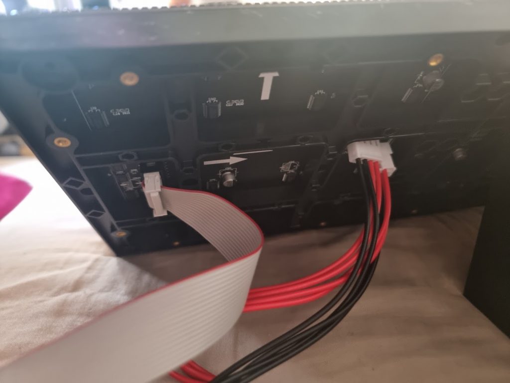
Here is a picture of the LED matrix connected to the bonnet. The white cable is the data cable (IDC cable) and the red/black cable is the DC power cable (red positive, black negative).
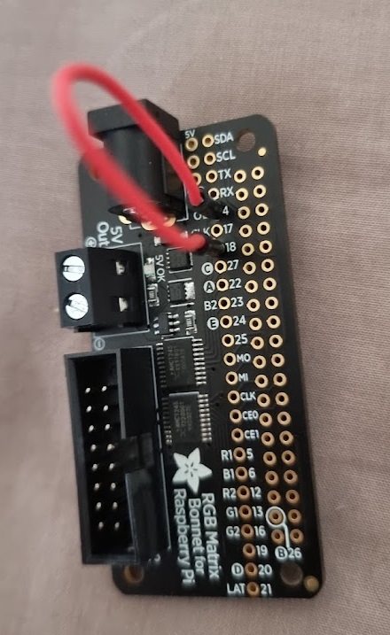
Adafruit RGB Matrix Bonnet for Raspberry Pi
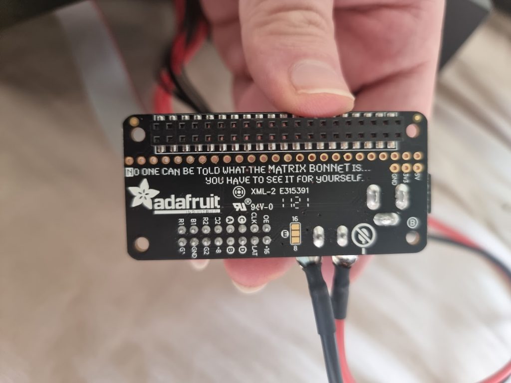
This handy bonnet from Adafruit simplifies the interfacing between our LED matrix and Raspberry Pi. The bonnet is able to power the LED matrix and also interface directly with a Raspberry Pi via a 40-pin GPIO connector. For this reason, I picked one up to make life easier. It is a bit of a tight fit between the bonnet and Raspberry Pi so I also picked up a spare 40-pin GPIO connector in case I needed it but in the end I did not end up using it.
Soldering to support the E-line
As my matrix has E line, I also have to solder the 8 on the Adafruit RGB Matrix bonnet to ground. Without this modification the LED pixels will be jumbled up.
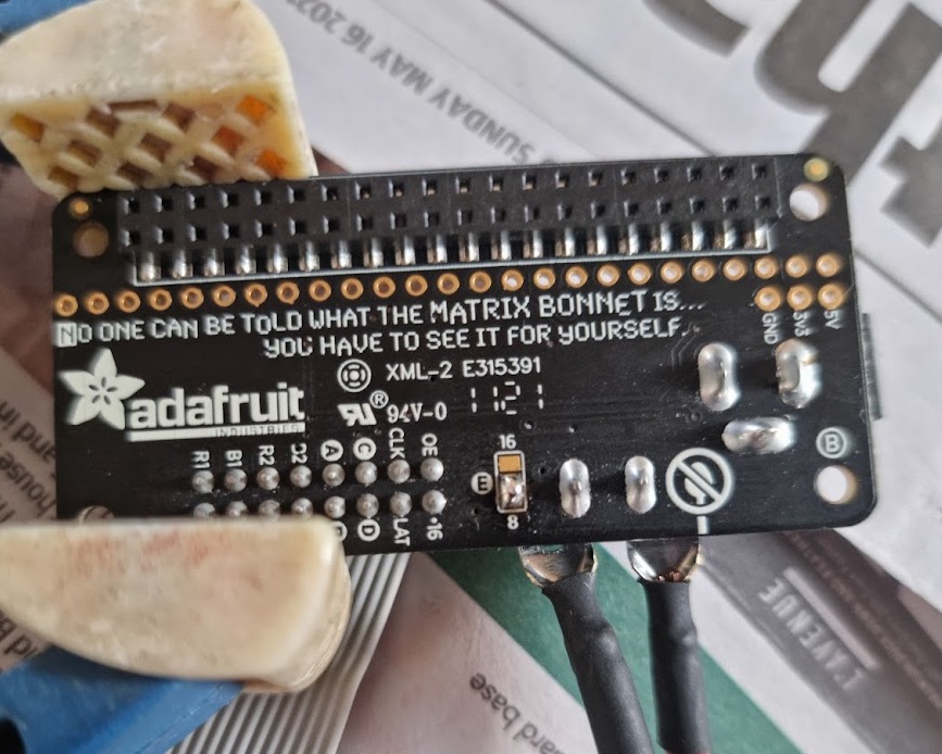
Fixing flickering issue (PWM Hardware fix)
One issue I noticed was a lot of flickering when using a lot of pixels on my LED matrix at the same time. For example, there would be some flickering every 10 seconds or so when displaying a picture.
This was solved by using a PWM hardware fix to ensure we have stable timings with no glitchy single lines.
I had to solder a cable from 18 to 4 on the bonnet.
There is some more context in this Github issue: https://github.com/hzeller/rpi-rgb-led-matrix/issues/1340
Raspberry Pi 4 Model B
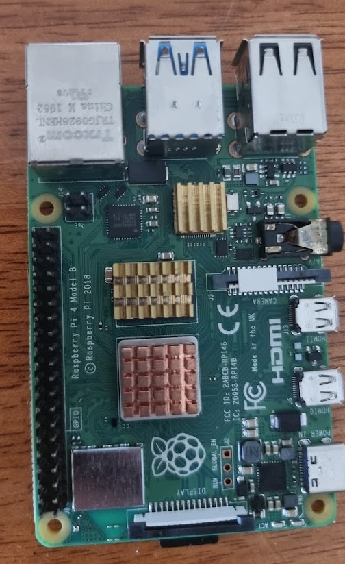
This RPi is overkill for this project as it is top of the line. However, I used it because I had a spare one that was unused. You want to make sure you use a RPi or other microprocessor that has sufficient memory to support quickly updating of the LED matrix (especially if your use case involves a lot of pixels are changing constantly like playing videos).
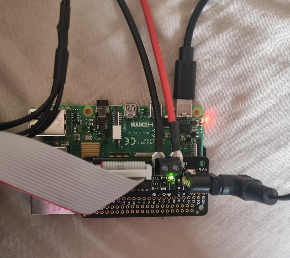
Bonnet + Raspberry Pi Connection
This is what the bonnet looks when its all wired up. We have the data (IDC) cable power cable plugged in. The power supply has the fork terminals connected and screwed in for the positive (red) and negative (black). The bonnet itself is then connected to the Raspberry Pi underneath it via the 40-pin GPIO connector. Also notice the incoming 2.1mm DC cable for powering the bonnet and USB Type-C cable for powering the Raspberry Pi.
Power Supply
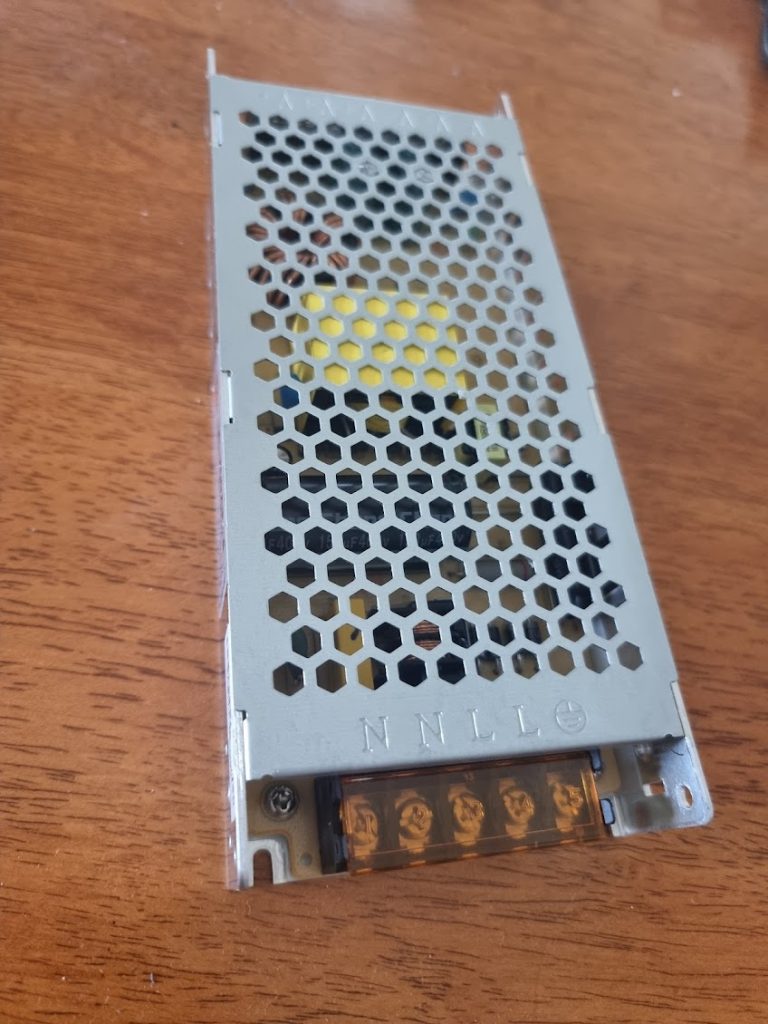
Our power supply is rated to input 220V AC and out provide upto 5V 40A DC of power.
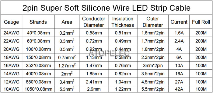
For the output wires that provide power to components, we must ensure we use the correct gauge (thickness of wire) to support the currents we need.
This handy table guesstimates these values:
Power Supply to Adafruit Bonnet (via DC 2.1mm Connector)
We have to send 5V 16A of power to the bonnet. For this reason we need to use a wire that has a gauge of 14 AWG and is rated for upto 16A of current.
We need to create our 14 AWG DC 2.1mm connector wire ourselves. This is quite a simple process.
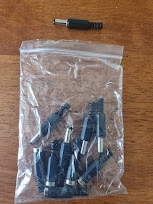
To wire up the 2.1mm DC connector, we can inspect the disassembled connector.
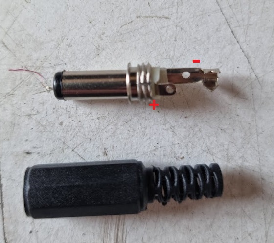
We have to wire up the positive wire to the small inside tip and the negative wire to the longer sleeve. We prepare two equal length 14AWG cables by skimming the ends of each end.
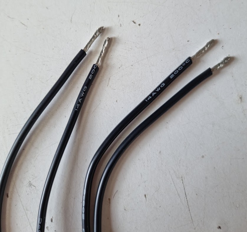
Next we solder up each wire (designating one as positive and one as negative). I use a red marker to label one of the cables as positive so I don’t forget when wiring up the other end.
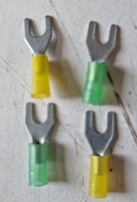
And this is the end result. There is a good opportunity here to use the heat shrink tubes around the end of the connectors. I also end up adding some fork terminals to the other end of the wire so they are easier to connect to the positive and negative outputs on the power supply.
This video may also help: https://www.youtube.com/watch?v=R_Q3tCGdW0o
Power Supply to Raspberry Pi (via USB Type-C Connector)
We have to send 5V 3A of power to our Raspberry Pi. For this reason we need to use a wire that has a gauge of 20 AWG and is rated for upto 4A of current.
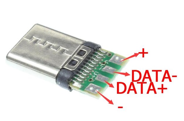
We need to create our 20AWG USB TYPE-C connector wire ourselves. This is quite a simple process.
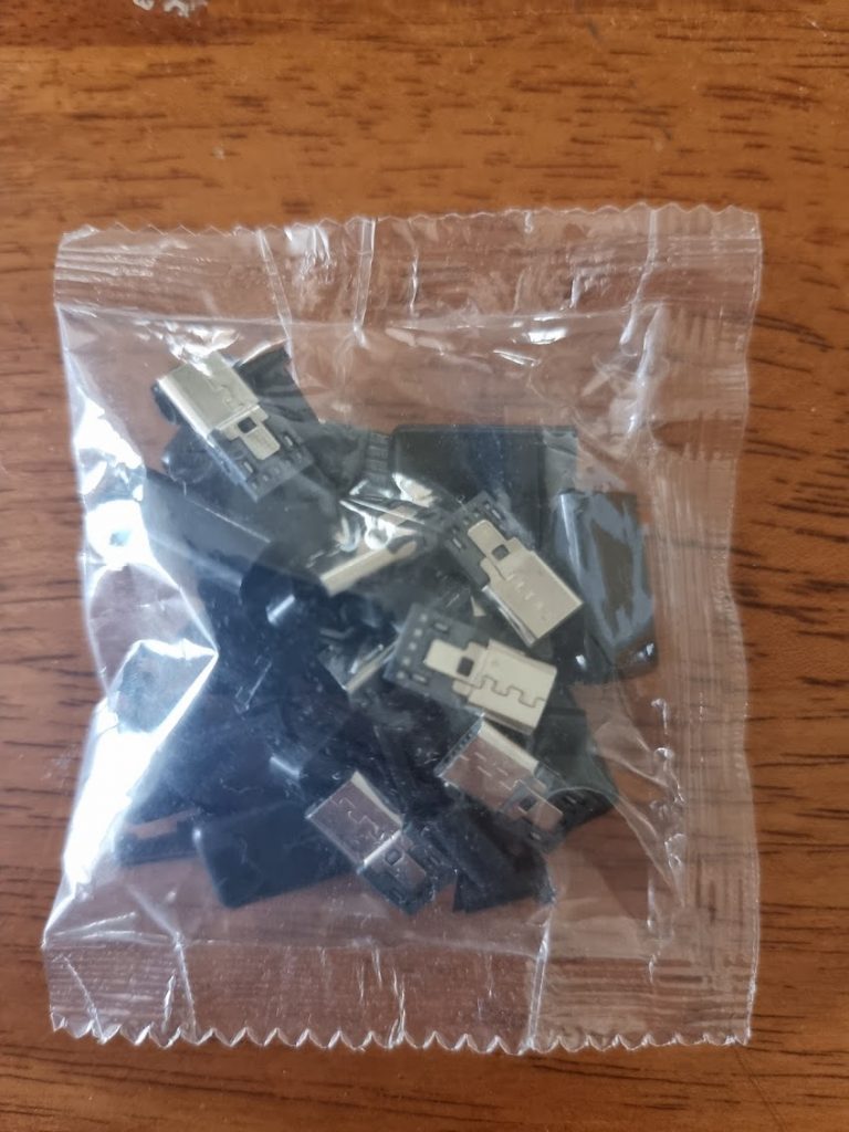
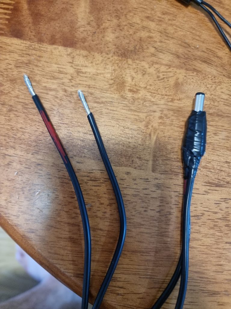
The process is similar. We take two equal length AWG20 cables and let one be the positive wire and one the negative wire. Our USB Type-C connector has four connection points. As we are not interested in transferring data and are using this cable solely to power our Raspberry Pi, we wire up the outer positive and negative connection points.
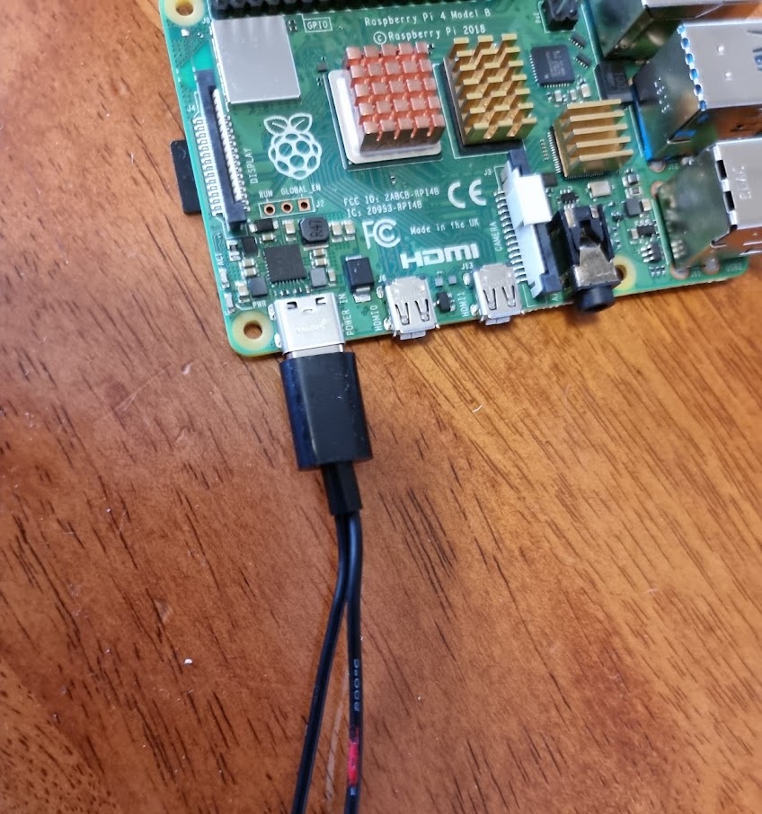
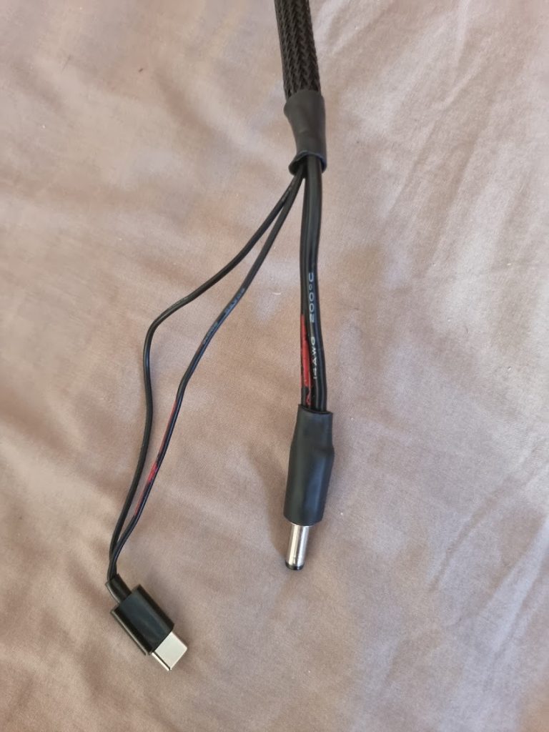
And this is the end result. Again make sure to mark the negative wire, use heat shrink tubes if needed and add fork terminals for easy interfacing with the powersupply!
Power Supply to Mains Power (via AU Computer Plug)
Finally, we need to wire up our power supply to the mains power. I live in Australia so this will be 230V AC.
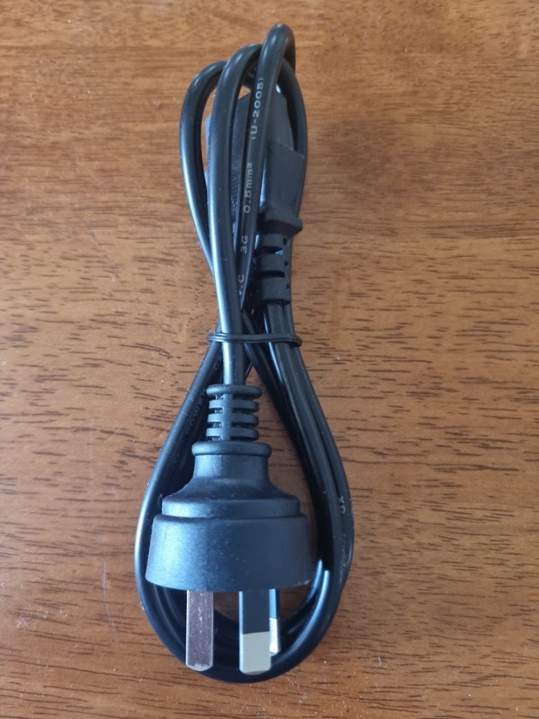
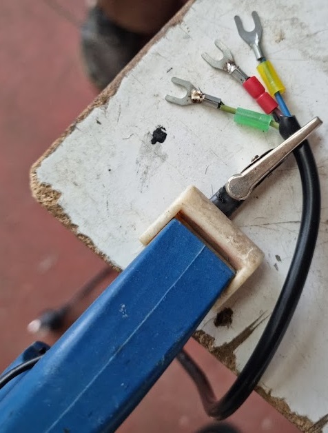
First start with a standard Australia computer plug:
Next we are going to cut off the IEC C13 end. Don’t cut too much wire off as we want to preserve the length of the wire. You will notice there are three wires inside, a green wire (ground), blue wire (neutral) and red wire (live). Skim these wires.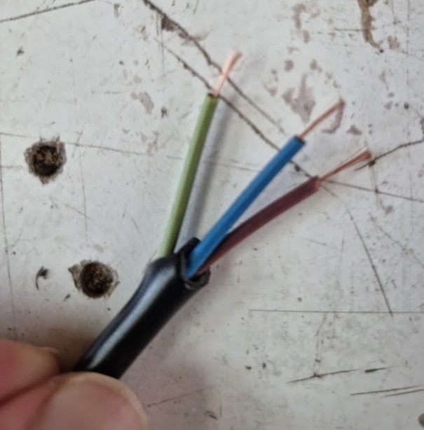
We are going to now add fork terminals to the each of the three wires as the wiring is quite thin and fragile otherwise. I used the fork terminals I already had and sadly didn’t have blue colour so I used yellow the neutral instead. Ideally you would match the colour of the wire to the fork terminal to prevent confusion.
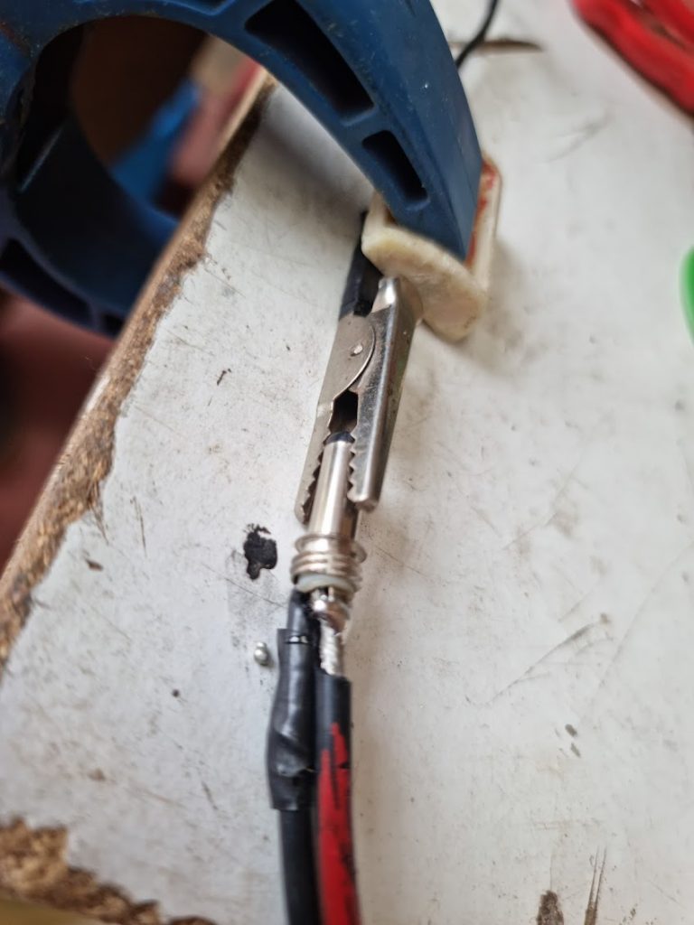
Finally, use some head shrink tubing around the spot you cut the wire to give it a premium feel enclosing. We can now wire up this cable to our power supply making sure we wire up ground, neutral and live correctly. We can then plug the other end into an outlet and use our multi-meter to do test the voltage to ensure we have 5V of power flowing through and out of the power supply.
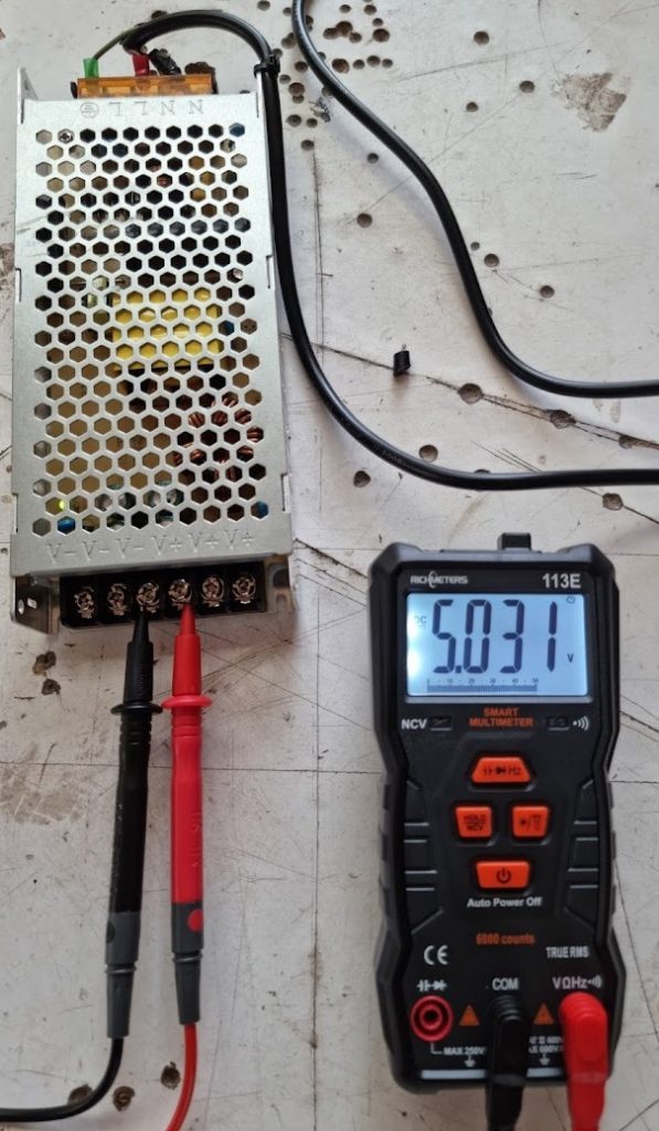
Hook up the multi-meter by connecting the red prong to positive and black prong to negative. We have 5.031 V flowing through which is within the safe range for a 5V power supply so everything looks good!
This video may also help: https://www.youtube.com/watch?v=Ls-6BeLHbA0
Power Supply Shielding
I also decided to use some aluminium to provide some shielding for the power supply in the off chance I spilled any liquid into it.

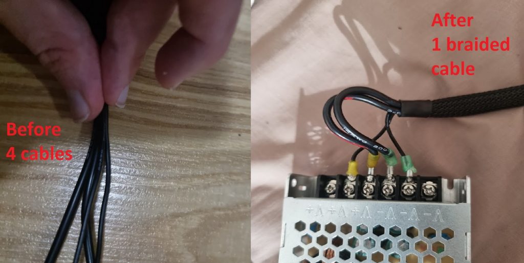
Braid Sleeving
One final step I completed was to use a braided sleeve for all of the cables I used. This turned 4 cables (2 for the 2.1mm DC connector cable and 2 for the USB Type-C connector cable) into a single (but thick) cable which is much nicer to handle.
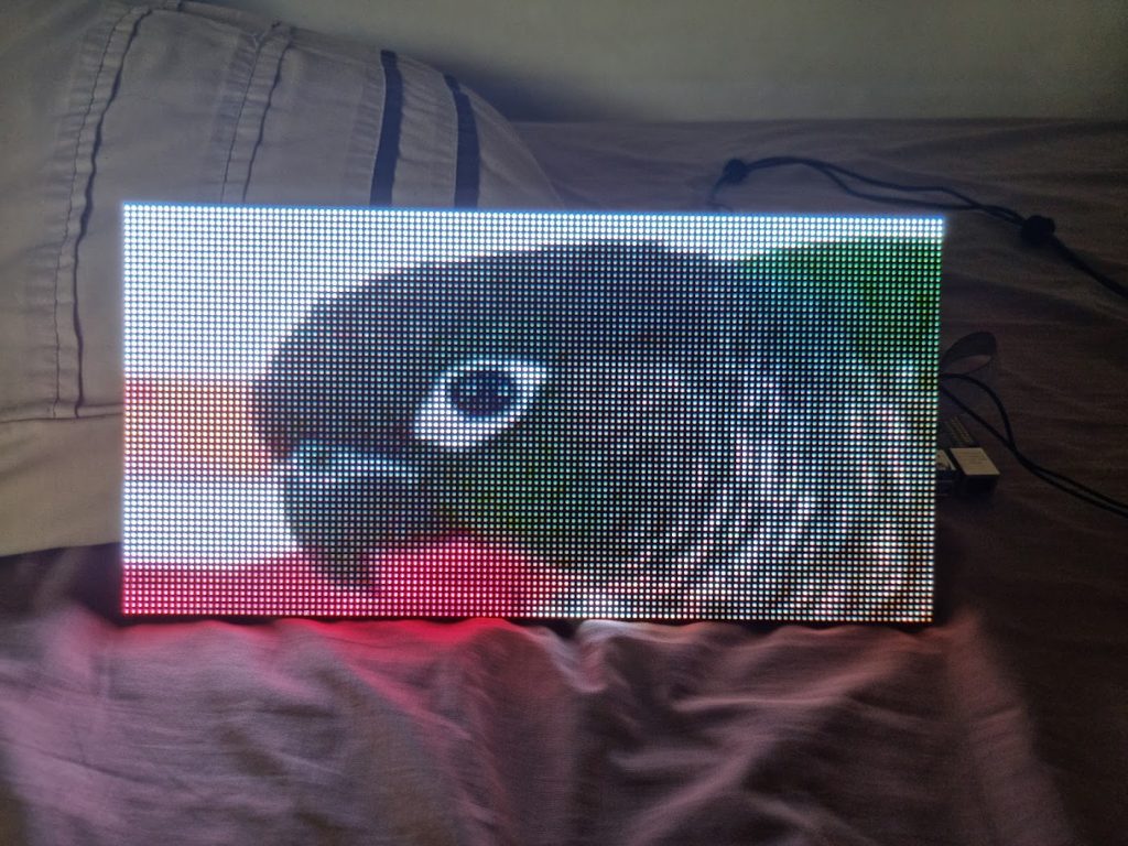
The first successful boot
After a lot of hard work, the LED matrix was working and we manage to get a picture to display!
Software
The Software used to send data to the matrix itself is powered by this open source software:
https://github.com/hzeller/rpi-rgb-led-matrix
Follow the README instructions on how to setup this software on your Raspberry Pi.
Here are the flags I used for my particular LED matrix and setup:
|
1 2 3 4 5 6 |
--led-rows=64 --led-cols=128 --led-gpio-mapping=adafruit-hat-pwm --led-slowdown-gpio=4 --led-panel-type=FM6126A --led-slowdown-gpio=4 |
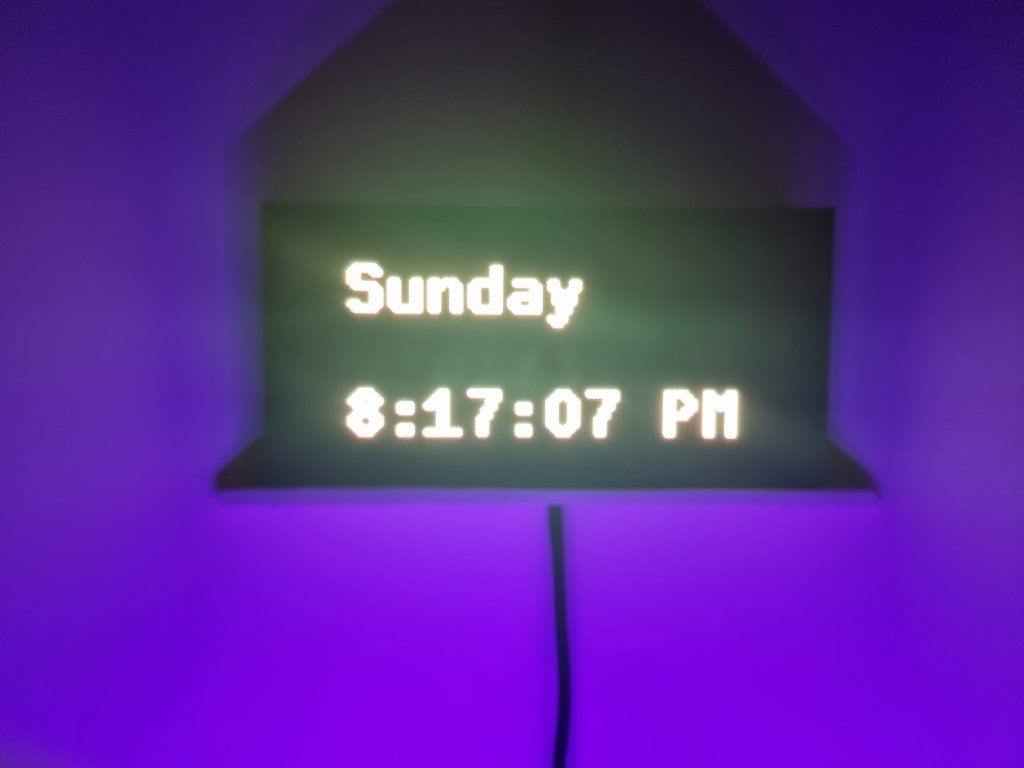
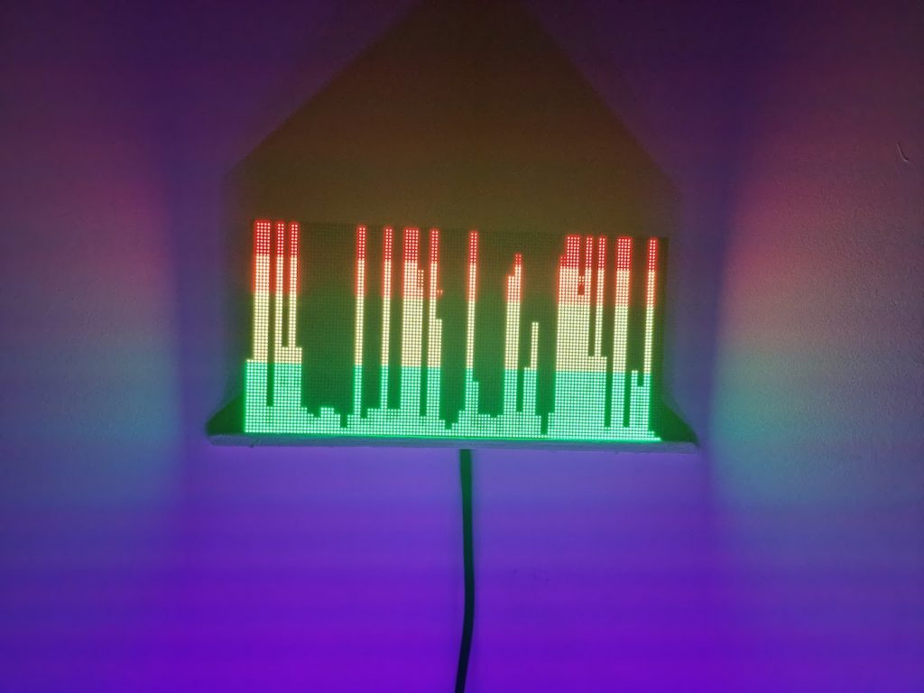
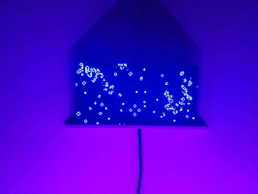
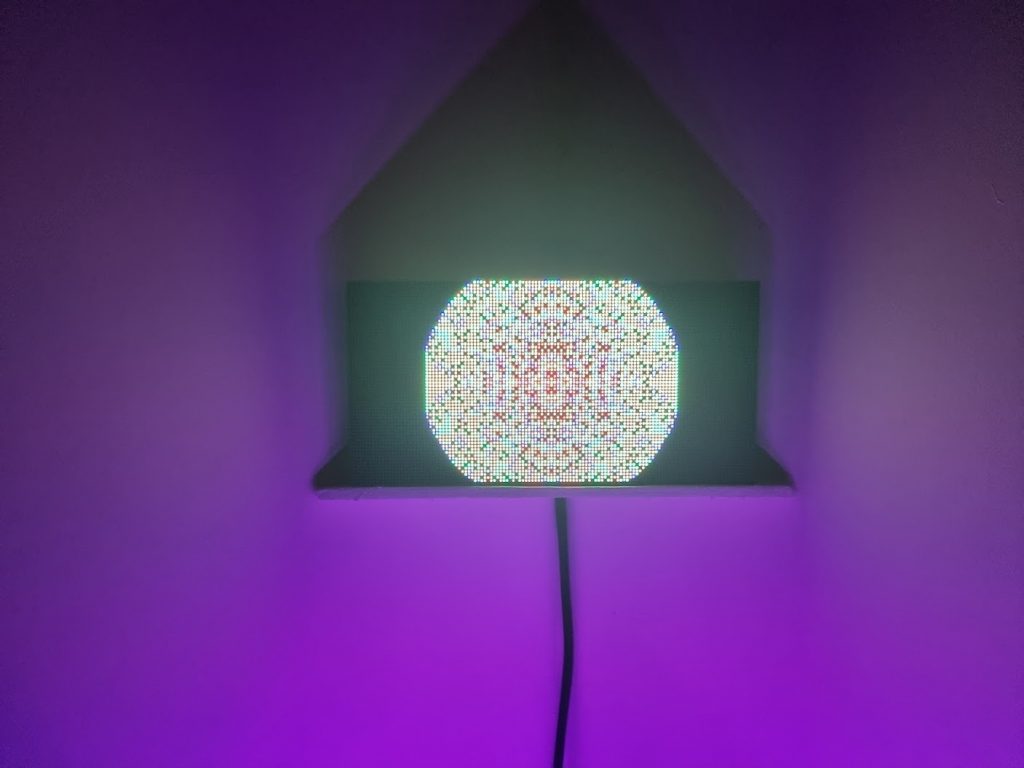
Final Product
I decided to place the LED matrix in the corner of a room on a shelf I made.
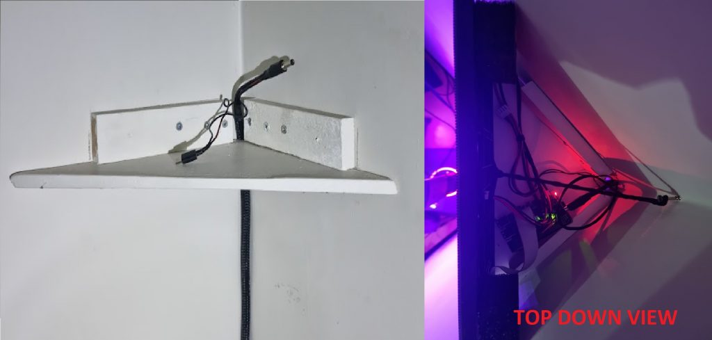
The end result is fantastic! Sadly, it doesn’t look very good in pictures but the display is amazing in-person!